Estimated Execution Times
Realistic estimates for an experienced general mechanic working on an I-PACE for the first time. Includes reading this guide, setup, and tea breaks.
Recommended split: Day 1 = Sections 1-4 (drain test, HV isolation, compressor swap). Day 2 = Sections 5-9 (recharge, park lock, final test). Sections 7 & 8 done while subframe is dropped — no extra time.
Latest Update — 17 March 2026 Action Required
Jaguar Recall Identified — H570 & H288
Jaguar have confirmed two open recalls against this vehicle:
| Campaign | System | Detail | Status |
|---|---|---|---|
| H570 | High Voltage Control System | Protective firmware update. Jaguar say this may be causing the shutdown/immobility issues. Requires dealer SDD/Pathfinder tool — cannot be done independently. | Acknowledged — NOT blocking current work |
| H288 | Park Lock Actuator | Corroded connector pins on park lock actuator. Recall covers actuator, wiring loom, and labour FREE. But requires dealer booking. | Acknowledged — NOT blocking current work |
Agreed Next Steps — For BPS to Action Now
- Order the parking actuator — Part T4K18381, genuine new, £340.65 from JLR Parts UK Ltd, Bromsgrove (10 in stock, FedEx delivery). Do NOT wait for the H288 recall — we are buying the part outright.
- Fit the new parking actuator — This resolves fault code P272C-13 (and should clear P303F-15 and P303F-29 as well). Straightforward swap, no dealer tools required.
- Fit the new AC compressor — Already purchased (£300). Procedure in Section 4 of this guide.
- Vacuum and recharge the AC system — 590g R1234yf. Procedure in Section 5.
- Reassemble and put the car back together — Subframe, undertray, wheels. Torques in Section 11.
- Clear all DTCs and test drive — U0080-87 and B1479-08 should clear once the park lock and compressor are resolved. Full test procedure in Section 9.
Parts to Order
| Part | Part Number | Cost | Source | Status |
|---|---|---|---|---|
| Park Lock Actuator | T4K18381 | £340.65 | JLR Parts UK Ltd, Bromsgrove — 10 in stock, FedEx | ORDER NOW |
| AC Compressor | — | £300 | — | ALREADY PURCHASED |
| HNBR O-Ring Kit | — | £8-16 | Amazon / Polymax | Confirm in stock |
| PAO 68 Oil 250ml | — | £6 | AutoAirConParts | Confirm in stock |
| R1234yf Refrigerant (590g) | — | £45-102 | AC Pro / FreezeECO | Confirm in stock |
Total additional spend: ~£400-465 (actuator + consumables). Compressor already paid for.
Diagnostic Status Current
What We Know
Vehicle arrived non-driveable. BPS charged the 12V battery and 8 of 13 DTCs cleared immediately. This confirms the HV battery (90 kWh) is healthy — the original fault codes were caused by the 12V going flat. The 5 remaining codes are the real issues.

Remaining DTCs — 5 Active Faults
Tools Required Full List
Essential Tools — Every Job
- Autel MaxiSys / iCarsoft i930 — Jaguar-capable diagnostic scanner. For DTCs, AC Service Mode, park lock calibration
- Torque wrench (small) — 5-50 Nm, 3/8" drive. AC pipes, terminals, small fasteners
- Torque wrench (large) — 40-200 Nm, 1/2" drive. Subframe, wheels, suspension
- Socket set — metric — 8, 10, 12, 13, 14, 15, 17, 18, 19, 21, 24mm. Both 3/8" and 1/2"
- Allen key / hex bit set — 4, 5, 6, 8, 10mm
- Torx bit set — T20, T25, T27, T30, T40, T45, T50, T55
- Combination spanners — 10-24mm metric
- Breaker bar — 1/2", 600mm. For stuck subframe bolts
- Multimeter — DC Amps (mA/A range) for drain test, voltage, continuity
- Trim removal kit — Plastic pry tools for interior panels
- Transmission jack / hydraulic table — Min 200kg rated. For subframe drop
- Axle stands (×4) — 3-tonne minimum
- Trolley jack — 3-tonne
- LED inspection light / headtorch — Magnetic LED bar ideal for underbody
HV Safety Equipment — Mandatory

- Class 0 insulated gloves — 1000V rated. MUST wear for any HV work. Not optional
- Leather outer gloves — Over the rubber gloves for puncture protection
- Safety glasses — Impact rated, arc flash protection
- HV warning sign — "VEHICLE ELECTRICALLY ACTIVE" for steering wheel
- Insulated tools — 1000V rated if working near HV connections directly
- Lockout/tagout kit — For SDU key. Tag with name and date
AC System Tools
- R1234yf recovery/recharge station — Must be R1234yf specific (NOT R134a)
- Electronic leak detector — R1234yf compatible
- New O-rings — R1234yf compatible for all AC connections
- PAO 68 compressor oil (SP-A2) — Only approved oil. 100ml total system capacity
- Measuring cylinder — For old compressor oil measurement
1. Moving the Vehicle Safety Critical ~30 min
Emergency Park Release (EPR) — Getting into Neutral
Vehicle cannot be driven. To roll it onto a ramp, release the parking pawl via the EPR lever in the frunk.

EPR Procedure
Electric Parking Brake (EPB) — Manual Release
If EPB is also locked on, manually release the rear calipers. Requires removing BOTH rear wheels.
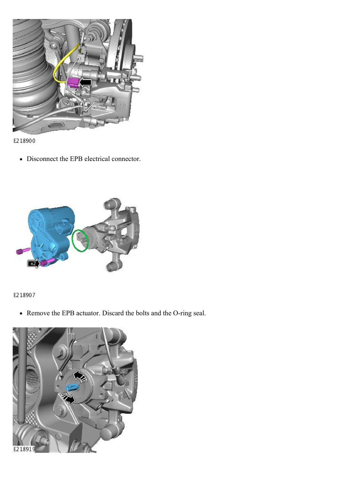
Manual EPB Release
2. 12V Parasitic Drain Investigation Priority ~45 min
Background
12V went flat causing all initial DTCs. Confirm whether there's a parasitic drain before doing anything else.

Drain Test Procedure
3. HV Safety — Full Power Down Must Do Before AC Work ~30 min
HV Isolation Procedure p.3570-3616


4. AC Compressor Removal & Installation Main Job 5-7 hours
Overview p.2904-2918
AC compressor sits on the front motor/drive unit. Access requires lowering front subframe by 80mm. New compressor already purchased (~£300 eBay).
Pre-Requisites
- HV system fully powered down (Section 3 — SDU key removed, verified 0V)
- AC refrigerant fully recovered (Section 5 — service mode required)
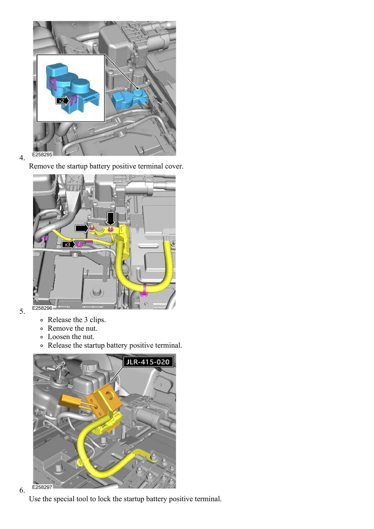
- 12V disconnected
- Vehicle on ramp or stands, wheels removed
Removal Procedure
Stage 1 — PPE & Access

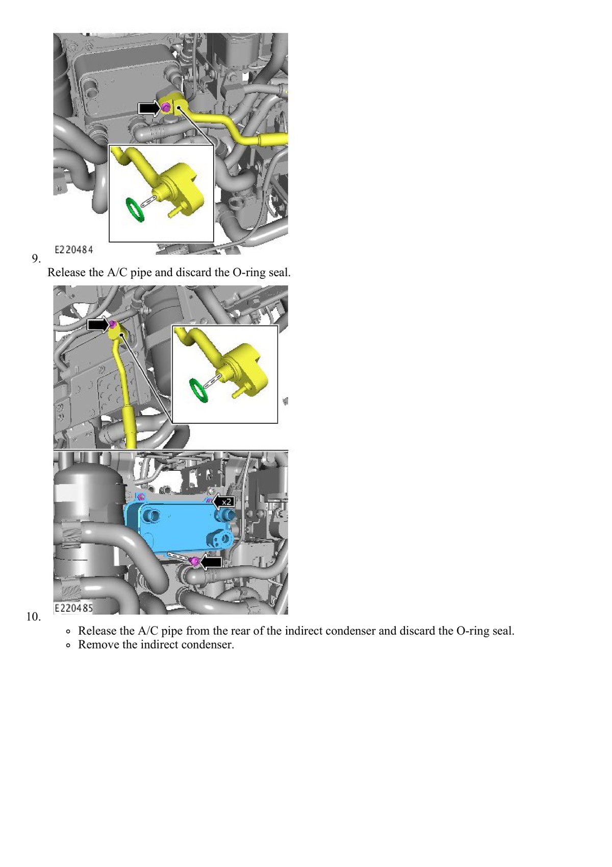
Stage 2 — AC Pipe Disconnection
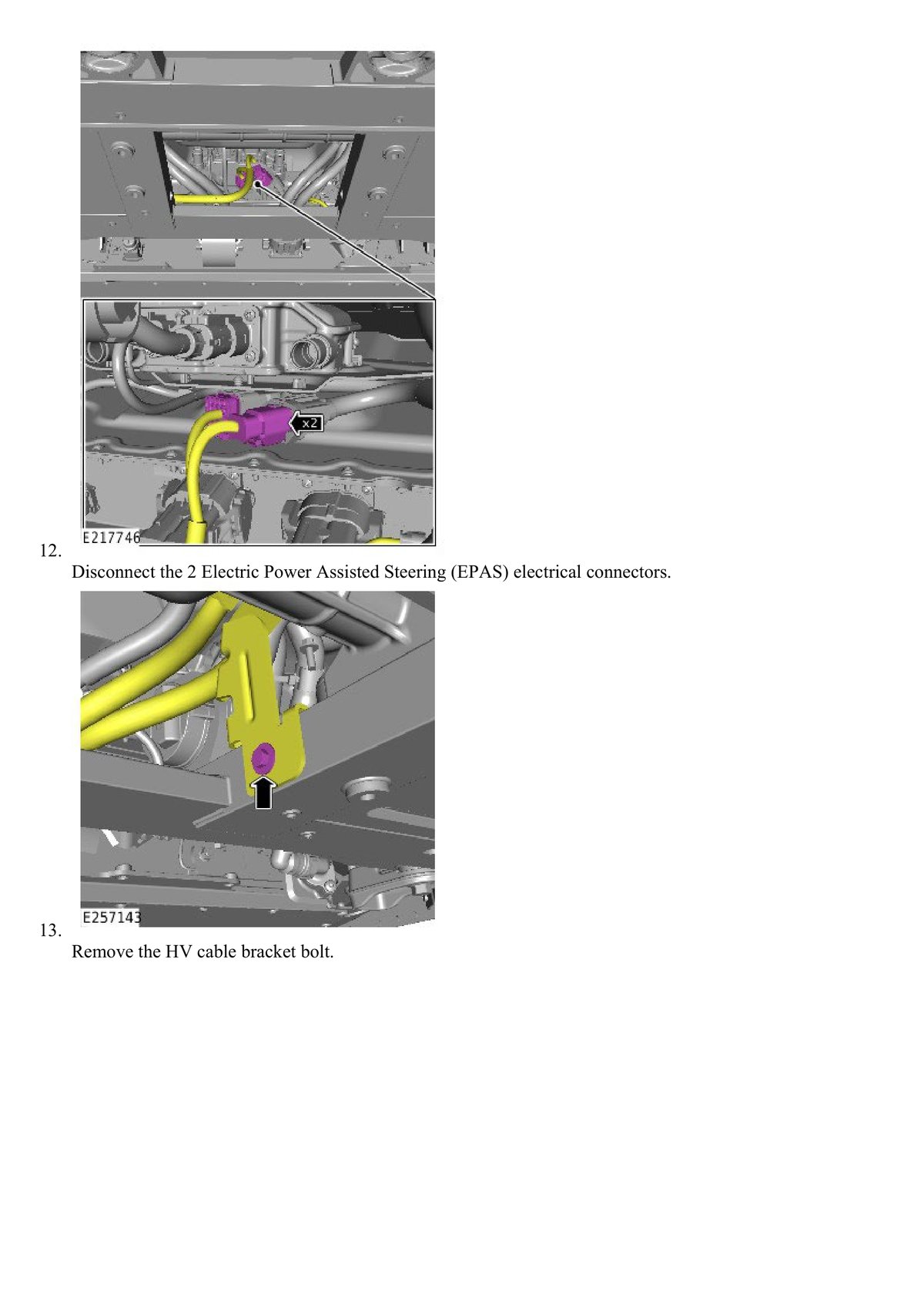

Stage 3 — HV Connector
Stage 4 — Lower Subframe 80mm

Stage 5 — Compressor Out

Installation Procedure

5. AC System Recovery, Vacuum & Recharge Specialist Equipment ~1.5 hours
Critical — Service Mode Required p.2790-2796

Service Mode Activation
Recovery (Before Compressor Removal)
Evacuation & Recharge (After Installation)

| AC Spec | Value |
|---|---|
| Refrigerant | R1234yf (NOT R134a) |
| Charge | 850g |
| Oil | PAO 68 (SP-A2) |
| Total Oil | 100ml |
| Vacuum | Below 500 microns, 30 min hold |
6. Park Lock Actuator Diagnostics Check & Test ~30 min
DTCs: P272C-13, P303F-15, P303F-29 p.755-756
All three relate to park lock. BPS reconnected the cable — may already be resolved.
7. Front Motor Plate Inspection While Subframe is Down ~15 min
Inspect While You're There p.2913

- Cracks around mounting bolt holes (aluminium fatigue)
- Corrosion / salt damage on lower subframe faces
- Loose or stretched bolts — replace if thread damage
- Rubber mount condition — splitting, cracking, oil contamination
8. LP Pipe Bracket — Known Recall Check While Open ~15 min
Technical Bulletin TB02109 / TB02087 p.3009-3013
Known JLR recall — original plastic LP pipe bracket fails, pipe vibrates and cracks.
9. Final Test Checklist Before Handback ~1 hour
Complete All Before Returning Vehicle
- HV re-enabled — SDU key refitted (clockwise to lock), rear seat reassembled
- 12V connected — 5 Nm, battery fully charged
- Powers on normally — correct dashboard sequence, no warning lights
- Full DTC scan — ALL modules — all 5 codes should be clear
- AC blows cold — max cold, fan high, vents reach 5-10°C
- No compressor noise — no grinding, rattling, or whine
- No AC leaks — detector on all joints, visual check for oil
- Park lock works — holds on slope, no DTC returns
- Test drive — brakes, steering, suspension, no vibrations
- All wheels torqued — 140 Nm (3-stage, star pattern)
- Undertray and liners refitted — all fasteners present
- 12V drain test passed — under 50mA after 30 min sleep
10. Specialist Parts to Source Prices March 2026
Standard consumables (brake cleaner, cable ties, copper grease, penetrating fluid, Loctite, etc.) — source from your normal motor factor. This list covers only the specialist/EV-specific items you won't have in stock.
AC Compressor
ALREADY PURCHASED (~£300 from eBay). Ensure it came with sealing gasket.
O-Ring Kit — HNBR Green (R1234yf Compatible)
Must be HNBR material, NOT standard NBR. HNBR is R1234yf safe; NBR degrades and causes leaks. Green colour = correct material.
| Option | Price | Link |
|---|---|---|
| Polymax 270pc HNBR Kit — 18 sizes, free UK shipping. Best value | £16.20 | Polymax Direct |
| Amazon UK 270pc HNBR Green Kit — check listing says "HNBR" not "NBR" | £8-15 | Amazon UK |
| eBay UK — various HNBR kits | £8-18 | eBay UK |
PAO 68 Compressor Oil (SP-A2 Rated)
Must be PAO 68, NOT PAG oil. PAG is electrically conductive — dangerous in HV EV systems. Total system capacity 100ml, but buy 250ml to have spare.
| Option | Price | Link |
|---|---|---|
| Auto Air Con Parts — SP-A2 Oil 250ml — Cheapest. Specialist AC supplier | £6.00 | AutoAirConParts |
| Arcomax PAO68 Universal 250ml — Dutch-made, R1234yf compatible | £6.50 | Arcomax |
| Arcomax PAO68 + UV Dye 250ml — same oil with leak detection dye. Worth the premium | £8-10 | eBay UK |
R1234yf Refrigerant — 850g Needed
R1234yf is regulated under UK F-Gas regs. 1kg retail cans don't exist in the UK — you get small DIY cans (170-500g) or trade cylinders (5kg+, needs F-Gas cert). You'll need ~850g total.
| Option | Price | Link |
|---|---|---|
| AC Pro R1234yf can — ~280-340g each. Need 3 cans. Made in Italy. Genuine product | £86-102/can | eBay UK |
| FreezeECO R1234YF 2-in-1 (gas + oil) 400ml — includes oil, up to 40% more gas | £45-55 | Amazon UK |
| Trade cylinder 5kg (if F-Gas certified) — by far cheapest per gram | £250-300 + £50 deposit | Sevac/AirConGas |
LP Pipe — T4K19719
Note: T4K19719 is the complete LP suction hose assembly (not just the bracket). If only the bracket clip is damaged, search separately for "I-PACE AC pipe clip bracket" (£5-15). Full hose only if pipe itself is cracked.
| Option | Price | Link |
|---|---|---|
| Genuine OEM T4K19719 (new) — eBay seller OEM_GENUINE_PARTS, 99.4% positive, Lithuania. Free tracked delivery. 60-day returns | £175.22 | eBay UK |
| Autodoc UK — range of I-PACE AC pipe parts | £4-137 | Autodoc |
| Jaguar dealer OEM | £200-350 | Phone local dealer with part number |
Park Lock Actuator — T4K18381 — IF NEEDED (Test First!)
Clear codes first (Section 6). Only buy if P272C returns after clearing. Also check Jaguar recall Campaign H288 — if your VIN is covered, the dealer replaces it FREE including the wiring loom.
| Option | Price | Link |
|---|---|---|
| Genuine New T4K18381 — JLR Parts UK Ltd, Bromsgrove. 10 in stock. FedEx delivery. Collection available | £340.65 | eBay UK |
| Used/breaker — rare, I-PACEs not commonly scrapped yet | £150-250 est. | 1st Choice |
| Jaguar dealer | £350-500 | Phone dealer — quote VIN for H288 recall check first |
HV Safety Gear (if not already owned)
| Option | Price | Link |
|---|---|---|
| CATU Presel GP-0 Class 0 Gloves — cheapest genuine option | £27.30 | SafetyGloves.co.uk |
| Polyco SuperGlove Volt Class 0 — well-known UK brand | £29.16 | SafetyGloves.co.uk |
| Warwick Test Supplies — Class 0, EV-specific | £38.76 | Warwick TS |
| Leather outer gloves (protectors) | £10-20 | Amazon UK |
Must be Class 0 (1000V AC). Class 00 is only 500V — not enough for EV work. Check for EN 60903 certification. Inspect for holes before every use (inflate and squeeze test).
Cost Summary
| Item | Budget | Mid-Range |
|---|---|---|
| AC Compressor | ALREADY BOUGHT — £300 | |
| HNBR O-Ring Kit | £8 (Amazon) | £16 (Polymax) |
| PAO 68 Oil 250ml | £6 (AutoAirConParts) | £6.50 (Arcomax) |
| R1234yf Refrigerant | £45-55 (DIY can) | £86-102 (AC Pro) |
| HV Gloves + Outers | £37 (CATU + leather) | £49 (Polyco + leather) |
| TOTAL (excl. compressor) | £96-114 | £158-174 |
LP pipe only if cracked (£175). Park lock actuator only if codes return (£340) — check H288 recall first (potentially FREE). These are worst-case additions.
11. Complete Torque Reference All Values
| Fastener | Torque | Notes |
|---|---|---|
| Front subframe bolts (×6) | 175 Nm + 90° | Angle-tighten. Cross pattern. p.2912 |
| Wheel nuts | 140 Nm | 3-stage: hand → 100 → 140 Nm. Star pattern. p.2046 |
| Steering rack bolts | 100 Nm + 90° | Angle-tighten. p.2913 |
| AC compressor mounting (×3) | 25 Nm | p.2915 |
| AC pipe connections | 9 Nm | New O-rings. Don't over-tighten. p.2793 |
| 12V battery terminals | 5 Nm | Petroleum jelly after. p.3309 |
| 12V battery clamp | 10 Nm | p.3311 |
| Brake caliper bolt (EPB) | 35 Nm | p.1261 |
| SDU panel (Torx T30) | 3 Nm | Finger-tight + snug |
| Undertray (Torx T30) | 5 Nm | Plastic — don't overtighten |
| Condenser connections | 9 Nm | If disturbed. New O-rings. p.2793 |
Workshop Manual Page Index Quick Reference
Where to Find It in the Manual
| Topic | Pages |
|---|---|
| Emergency Park Release (EPR) | p.1256-1258 |
| Electric Parking Brake manual release | p.1259-1263 |
| Park Lock DTC diagnosis (P272C) | p.755-756 |
| Wheel nut torque specs | p.2046 |
| AC system recovery & recharge | p.2790-2792 |
| AC system specs & torques | p.2793-2796 |
| AC compressor removal & installation | p.2904-2918 |
| LP pipe & bracket (TB02109) | p.3009-3013 |
| 12V battery disconnect/reconnect | p.3309-3312 |
| HV safety — full power down | p.3570-3616 |
All diagrams and procedures from JLR Workshop Manual — Jaguar I-PACE X590 (2018-2024), 8,785 pages.
Guide prepared by Ade Whetton for BPS Garage Services — March 2026